Alternator wiring

Renault & Alpine General Discussion

Moderators: eastlmark, BIG_MVS, phildini, Test Moderator, Alpineandy

no avatar
User

rupert

Rank

Non Member

Posts

1323

Joined

Mon Apr 19, 2004 7:39 pm

Location

Plymouth, Devon


Has thanked: 2 times
Been thanked: 9 times

Alternator wiring

Postby rupert » Sat Oct 15, 2011 12:40 pm

Okay, so the big red one goes to the +ve post - easy.

What about the other two? How do you test which way round they are and which terminal they go to?
User avatar
User

JohnC

Rank

Non Member

Posts

2120

Joined

Sun Dec 02, 2007 6:19 pm

Location

Jersey C.I.


Has thanked: 15 times
Been thanked: 83 times

Postby JohnC » Sat Oct 15, 2011 5:36 pm

Rupert, not too sure which two leads you are talking about....any chance of a pic of the leads? ......is the surpressor ones?.... There is also an Earth lead which needs attaching though.
1990 GTA Atmo, 2003 Jaguar X type 2.5SE Auto, 2018 Kia Picanto GT-Line-S 1.25
no avatar
User

rupert

Rank

Non Member

Posts

1323

Joined

Mon Apr 19, 2004 7:39 pm

Location

Plymouth, Devon


Has thanked: 2 times
Been thanked: 9 times

Postby rupert » Sat Oct 15, 2011 8:27 pm

One this wire for the post connector. There are also two small wires.

One is to do with the dash warning light, the other is possibly an earth. Never really paid attention to them til I got them the wrong way round today on the newly refurbished alternator.

DOH!

Little wisp of blue smoke and a dead regulator I guess.

So I won't be going to the Northern meet tomorrow then.
User avatar
User

The Saint

Rank

Administrator

Posts

1128

Joined

Thu Sep 08, 2011 11:55 am

Location

Rugby Warwickshire


Has thanked: 57 times
Been thanked: 45 times

Postby The Saint » Sat Oct 15, 2011 9:33 pm

The 2 smaller wires are one for the charge warning light, and the other a switched battery live feed from the ignition switch to tell the alternator that you have switched the ignition on and to allow the system to accept that charge.
The Saint.
Blue A610,
Black Smart Roadster.
SmartEDElectric Drive
User avatar
User

JohnC

Rank

Non Member

Posts

2120

Joined

Sun Dec 02, 2007 6:19 pm

Location

Jersey C.I.


Has thanked: 15 times
Been thanked: 83 times

Postby JohnC » Sat Oct 15, 2011 10:06 pm

Rupert, these two wires are normally terminated in a keyed connector which you should not be able to plug in the wrong way around. The connector pins are numbered, and in Pin 1, there should be a Yellow wire, and in Pin 2, there should be a White with a Blue tracer, if you are trying to wire this up without the connector, if you look carefully there might be the numbers marked on the Alt`s socket.
The Earth lead is not that small and is Black, and just goes to a convenient nut on the body of the Alt.
There are only 4 connections to the Alt, Red +, & Black -, and the two in the connector,.... if a suppressor is fitted, Red wire to Red + on the Alt, and either it is just bolted together with the earth connection, or if it has a separate black wire, it goes to the earth connection.
1990 GTA Atmo, 2003 Jaguar X type 2.5SE Auto, 2018 Kia Picanto GT-Line-S 1.25
User avatar
User

si21

Rank

Non Member

Posts

2094

Joined

Mon May 09, 2005 8:24 pm

Location

S.E London


Has thanked: 3 times
Been thanked: 2 times

Postby si21 » Sun Oct 16, 2011 9:48 am

JohnC wrote:Rupert, these two wires are normally terminated in a keyed connector which you should not be able to plug in the wrong way around. The connector pins are numbered, and in Pin 1, there should be a Yellow wire, and in Pin 2, there should be a White with a Blue tracer, if you are trying to wire this up without the connector, if you look carefully there might be the numbers marked on the Alt`s socket.
The Earth lead is not that small and is Black, and just goes to a convenient nut on the body of the Alt.
There are only 4 connections to the Alt, Red +, & Black -, and the two in the connector,.... if a suppressor is fitted, Red wire to Red + on the Alt, and either it is just bolted together with the earth connection, or if it has a separate black wire, it goes to the earth connection.


Unfortunately John we have not owned our cars from new and the plug quality is as useful as a choclate Teapot. The connection being very unreliable therefore the plug being cut off and two new seperate connections are fitted these can then be fitted either way round. I have replaced the complete loom so.i.have different colout wires so my configuration will not relate to.Ruperts car my leads are also marked up so.as.to avoid confusion. Due to you 3 branch headers my alternator is buried under a heat sheild and the loom is also wrapped; Rupert with your setup I strongly recommend you do.the same. I heard after a recent alternator scare that Ian Blacks 24 valve lump regularly fries alternator; I have also wrapped the starter too :wink:

To win the race you first have to cross the line.

Si21
no avatar
User

E M Wynne

Rank

Non Member

Posts

83

Joined

Mon May 07, 2007 5:30 pm


Has thanked: 0 time
Been thanked: 0 time

alternaters

Postby E M Wynne » Mon Oct 17, 2011 11:04 am

On my 24vl. I moved the Alt. to the top off the left-hand cam. cover...no more fried Alt. & still uses the std. belt...with modified turbo tensioner...it can take the strain , as the airco. pump normally sits there.
Eddie.
User avatar
User

JohnC

Rank

Non Member

Posts

2120

Joined

Sun Dec 02, 2007 6:19 pm

Location

Jersey C.I.


Has thanked: 15 times
Been thanked: 83 times

Postby JohnC » Mon Oct 17, 2011 12:17 pm

si21 wrote:......The connection being very unreliable therefore the plug being cut off and two new separate connections are fitted these can then be fitted either way round.
Thanks Si for a possible explanation, however, the male spades in the regulator connection are different sizes, a 1/4 in, and a 3/16 in... or the metric equivalent. If, as you say, one has not got the original lead colours, this does throw up a dilemma. When you switch on the ign, both wires will show 12 volts, now one is coming from the battery direct, and the other via the ign light. You would think that the ign light wire would have a voltage lower than the battery one, but because a meter draws little or no current, there will not be a voltage drop across the light hence they will both read battery voltage.
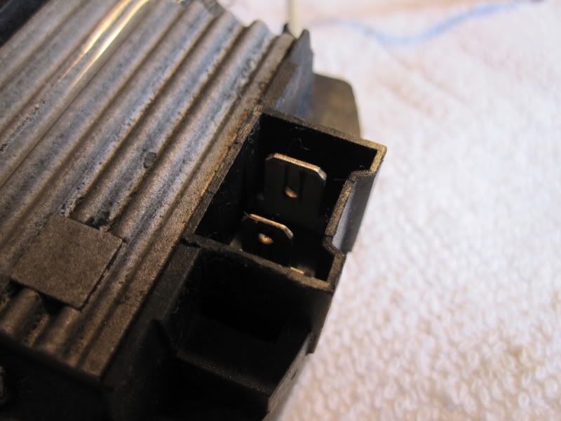
The only safe way to identify each lead is to get hold of a 12v torch type bulb and with ign on, hold one of the wires against the brass thread, and touch the soldered center pip of the bulb to earth. With one of the wires, the bulb will light brightly, and with the other wire, the bulb will half light and so will the ign lamp. Having identified which wire is which, the one that lit only the bulb, needs a 3/16 in female spade crimp attached to it and connected to its 3/16 in male spade in the regulator, and the one that lit both lamps needs a 1/4 in female spade crimped to it and connected to the 1/4 in male spade.
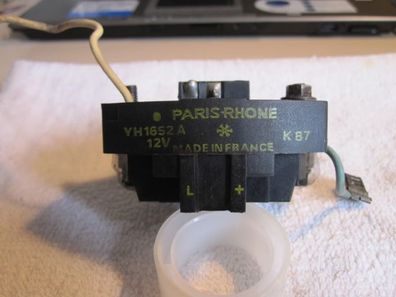
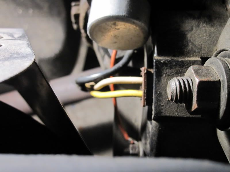
I have taken a few pics which are posted below which should help identify the parts, note my old regulator shows a + and an L, which is +, direct to the battery, and L which goes to the lamp, (clever stuff this :roll: ) also a pic of the original Yellow and White leads entering my Regulator, the Yellow wire being the wire that goes to the Battery.

Image
Image
Image
1990 GTA Atmo, 2003 Jaguar X type 2.5SE Auto, 2018 Kia Picanto GT-Line-S 1.25
User avatar
User

si21

Rank

Non Member

Posts

2094

Joined

Mon May 09, 2005 8:24 pm

Location

S.E London


Has thanked: 3 times
Been thanked: 2 times

Postby si21 » Mon Oct 17, 2011 4:24 pm

JohnC wrote:
si21 wrote:......The connection being very unreliable therefore the plug being cut off and two new separate connections are fitted these can then be fitted either way round.
Thanks Si for a possible explanation, however, the male spades in the regulator connection are different sizes, a 1/4 in, and a 3/16 in... or the metric equivalent.

The problem being is that you always end up using whats available to you at the time :roll: ; so modding the clips to fit as best and as tight as possible e.g. replacement connectors never seem to be the exact size. I suppose it's much better if you can seperate the original connectors from the plug and make good, but I think mine were better than usless, hence the new not so accurate for fit items. :lol: :lol:

si21


  • Advertisement

Who is online

Users browsing this forum: No registered users and 221 guests

Powered by phpBB ® | Renault' and 'Alpine' are trademarks of Renault S.A.S. or its subsidiaries and are used with kind permission of Renault France